
Fisher Paykel Refrigerator Problems RF201A
Service manual RF201A
Fisher Paykel refrigerator problems RF201A
IMPORTANT SAFETY INSTRUCTIONS
CAUTION: This machine must be electrically grounded. It can be grounded through the grounding lead in the 3-prong power cord, if plugged into a properly grounded appliance outlet or through a separate No. 13 or large wire from the cabinet to an established ground. In all cases the grounding method must comply with any local electrical code requirements. Certain internal parts are internationally NOT GROUNDED and may present a risk of electrical shock only during servicing. To reduce the risk of shock, disconnect the power supply cord before servicing.
CAUTION: ALL TERMINALS AND INTERNAL PARTS SHOULD BE TREATED AS LIVE.
IMPORTANT – RE-CONNECT ALL GROUNDING DEVICES.
If grounding wires, screws, straps, clips, nuts or washers used to complete a path to ground are removed for service, they must be returned to their original position and properly fastened.
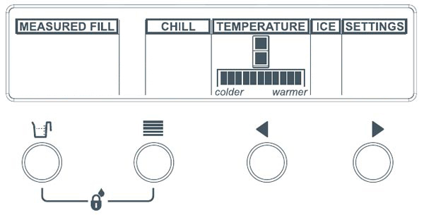
Key presses
Function: Key silent mode
Key presses: Menu ![]()
Action: On/Off
Press time: Hold down for 4 seconds
Function: Key & dispencer lock
Key presses: Menu + Measured fill ![]()
Action: On/Off
Press time: Hold down for 2 seconds
Function: Key lock
Key presses: Menu + Measured fill ![]()
Action: On/Off
Press time: Hold down for 4 seconds
Function: Diagnostic mode
Key presses: Menu + Up ![]()
Action: On
Press time: Hold down for 4 seconds
Function: Forced defrost
Key presses: Menu + Down ![]()
Action: On
Press time: Hold down for 4 seconds
Function: Sabbath mode
Key presses: Menu + Measured fill + Down ![]()
Action: On/Off
Press time: Hold down for 4 seconds
Function: Disable filter alarm
Key presses: Menu + Measured fill + Up ![]()
Action: On/Off
Press time: Hold down for 4 seconds
Function: Show Off Mode
Key presses: Menu + Down + Up ![]()
Action: On/Off
Press time: Hold down for 4 seconds
Function: Flowmeter calibration
Key presses: Measured fill + Down ![]()
Action: On
Press time: Hold down for 4 seconds
Function: Filter reset
Key presses: Measured fill + Up ![]()
Action: Reset
Press time: Hold down for 4 seconds
Function: Force ecemaker manual
Key presses: Measured fill + Down + Up ![]()
Action: Activates once
Press time: Hold down for 4 seconds
Temperature Settings
PC Setting: Colder – Warmer
32F, 32.9F, 33.8F, 34.7F, 35.6F, 37.4F, 39.2F, 41.0F, 42.8F, 44.6F, 46.4F
FC Setting: Colder – Warmer
-5.8F, -5.8F, -4.0F, -3.1F, -1.3F, 0.0F, 1.4F, 2.3F, 4.1F, 5F, 6.8F
Temperature Settings
Press the MENU button until the Temperature Icon is highlighted. The refrigerator Icon shall be highlighted as well. By pressing the UP or DOWN will change the temperature of the PC. By pressing the MENU button again the FC section of the refrigerator will be highlighted. By pressing the UP or DOWN button will change the temperature of the FC. The factory default seitting are 34.7°F PC and 0° F for the FC.
Input/Output Status
To enter input / output status:
- Press and hold the MENU button, then press the UP button for 4 seconds. This enters Diagnostic mode.
- Press the UP button three times. The current input /output status will be displayed.
If a device is on or a door is open, the respective LCD will be on. Return to normal operation by pressing the MENU button. Note: Only the first 6 LCD’s are used. The last 5 are not used.

Electronic / Electrical Faults:
Ice & Water products have the LED display on the door. A wrench symbol and LCD fault code will appear automatically if there’is a fault in the temperature measuring system, defrost system, fans or low ambient heater.
Fault Codes:
A wrench symbol and LCD fault code will appear automatically if there is a fault in the temperature measuring system, defrost system, fans or low ambient heater. When the PC door is opened an alarm will sound, the number of beeps also indicates the fault code.

Fault Code 1
Reason: On last power up, the power module failed self test. Primary Action: Replace power module.
Fault Code 2
Reason: The previous 2 defrosts were aborted after 30 minutes. Primary Action: Check defrost element.
Fault Code 3
Reason: The resistance of all the temperature sensors Is outside the normal range (>45K Ohms). Primary Action: Check 6-way Rast connector at power module.
Fault Code 4
Reason: The resistance of all the temperature sensors is outside the normal range (< 660 Ohms). Primary Action: Check 6-way Rast connector at power module.
Fault Code 5
Reason: The resistance of the FC sensors is outside the normal range (>45K Ohms). Primary Action: Check sensor connector at power module.
Fault Code 6
Reason: The resistance of the FC sensors is outside the normal range (<660 Ohms). Primary Action: Check sensor connector at power module.
Fault Code 7
Reason: The resistance of the Defrost sensor is outside the normal range (>45K Ohms). Primary Action: Check sensor connector at power module.
Fault Code 8
Reason: The resistance of the Defrost sensor is outside the normal range (<660 Ohms). Primary Action: Check sensor connector.
Fault Code 9
Reason: The resistance of the PC sensors is outside the normal range (>45K Ohms). Primary Action: Check sensor connector.
Fault Code 10
Reason: The resistance of the PC sensors is outside the normal range (<660 Ohms). Primary Action: Check sensor connector.
FaultCode 11
Reason: The current for the LAH, PC &FC Fan is lower than expected. Primary Action: Check the 6 way fan/LAH, connector at module.
Fault Code 12
Reason: The current for the LAH, PC &FC Fan is higher than expected. Primary Action: Check the 6 way fan/LAH, connector at module.
Fault Code 13
Reason: LAH is drawing less current than expected. Primary Action: LAH open circuit.
Fault Code 14
Reason: LAH is drawing higher current than expected. Primary Action: Check wiring connection.
Fault Code 15
Reason: PC fan is drawing less current than expected. Primary Action: PC fan open circuit.
Fault Code 16
Reason: PC fan is drawing higher than expected current. Primary Action: Check fan wiring or connections.
Fault Code 17
Reason: FC fan is drawing less current than expected. Primary Action: FC fan open circuit.
Fault Code 18
Reason: FC fan is drawing higher current than expected. Primary Action: Check FC fan & wiring circuit.
Fault Code 19
Reserved.
Fault Code 20
Reason: Flapper heater current low. Primary Action: Check for short circuit.
Fault Code 21
Reason: Flapper current high. Primary action: Check for short circuit.
Fault Code 22
Reason: PC 2 sensor outside limit(>45K Ohms). Primary action: Check connection at module.
Fault Code 23
Reason: PC 2 sensor outside limit (<660 Ohms). Primary action: Check connection at module.
Fault Code 24
Reason: IM sensor outside limit(>45K Ohms). Primary action: Check connection at module.
Fault Code 25
Reason: IM sensor outside limit(<660 Ohms). Primary action: Check connection at module.
Fault Code 26
Reason: IM Motor timed out. Primary action: check gearbox operation.
Fault Code 27
Reason: IM Motor current too high. Primary action: check for obstruction.
Fault Code 28
Reason: IM Water solenoid current high. Primary action: check solenoid resistance.
Fault Code 29
Reason: IM Water solenoid current low. Primary action: open circuit solenoid.
Fault Code 30
Reason: No display signal. Primary action: check short/broken wire.
Fault Code 31
Reason: No display signal. Primary action: Check snort clock/data line.
Fault Code 40
Reason: IM Solenoid Short circuit Transistor 1. Primary action: check solenoid resistance.
Fault Code 41
Reason: IM Solenoid Short circuit Transistor 2. Primary action: Check connections.
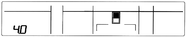
Diagnostic Mode
To enter diagnostic modes, press and hold the MENU button, then press the UP button for 4 seconds. The PCtemperature will be displayed on the LCD as shown below. The actual temperature of the PC is shown. Note Temperatures are shown in Degrees Centigrade.
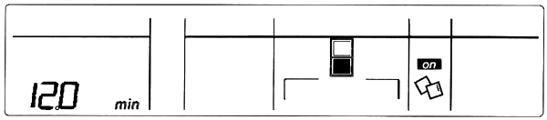
PC Sensor Temperature By pressing the Up button once more, this will indicate the FC sensor temperature. Note: The “min” indicates minus 12°C

FC Sensor Temperature By pressing the Up button once more, this will indicate the Defrost sensor temperature.

Defrost Sensor Temperature By pressing the Up button once more, this will indicate the input/Output Status.

Input/Output Status Press UP one more time, LCD displays.

PC2 Sensor Press up one more time and Ice maker temperature is shown.
Icemaker Sensor Press UP one more time and fault history will be shown.
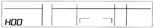
Fault History To exit diagnostic mode press MENU button
Data Download
To place the product into download mode, press and hold the MENU button, then press the UP button for four seconds, then press DOWN button. Once the product is in a download mode, either of the LEDs can be used. Place the download pen towards the LEDs and start the download. The display wiii have the letters “dl” signifying product is in a download mode.

Download
Compressor Information
Fisher & Paykel Active Smart Refrigerators are fitted with a Variable Speed Compressor (Commonly known as variable capacity compressor or VCC). VCC’s run on DC voltage supplied from an inverter and are operate at different speeds to vary the amount of cooling capacity in the refrigerator. Inverters convert AC mains power voltage supply to DC voltage supply which is varied to control the compressor speed. Compressor winding are a 3 phase configured motor and external testers should not be used. Resistance between each pin should be 6.4Ohm DISCONNECT PRODUCT FROM POWER SOURCE BEFORE TESTING THE PRODUCT.